Bios settings - Detailed instructions in pictures. Setting up the BIOS in pictures: step-by-step instructions on the correct parameters How to enable additional settings in the BIOS
Hi all! In this article I will describe and translate all the important points and sections of the AWARD BIOS. Let's look at the BIOS of this manufacturer using the "Award Modular BIOS v6.00 PG" version as an example.
So, let's begin...
In order to enter the BIOS on your “machine”, you must - after turning on the computer - press the key
Control in the BIOS is carried out by the following keys (I will describe only the main ones):
<>, <↓>, <←>, <→>- moving through points;
- select the desired section/item;
- in the main menu, exit the BIOS, where a notification appears “about accepting and saving the current settings” on or “cancel”. It is also used to exit sections to the main BIOS menu.
<+/PgUp>- change item settings (up);
<-/PgDn>- change item settings (down);
<+>and - work only on Num Lock;
- setting secure BIOS settings;
- installation of optimized BIOS settings;
- save or not save changes in the BIOS (- yes, - no), then exit the BIOS.
And so you entered the BIOS and became familiar with the control keys. Now we will consider all the main sections of this BIOS version. Naturally, let's start with the main menu.
1. Standard CMOS Features
2. Advanced BIOS Features
3. Integrated Peripherals
4. Power Management Setup
5. PnP/PCI Configurations (PNP/PCI Service Configuration) so this function has lost its relevance in our time, I won’t even consider this small section (setting up interruptions for cards installed in PCI slots) in the options of this section we set Auto.
6. PC Health Status
7. Frequency/Voltage Control (Control of voltages and operating frequencies of devices)
8. Load Fail-Safe Defaults.
9. Load Optimized Defaults
10. Set Supervisor Password
11. Set User Password
And so we figured out the meaning of the sections of the Main Menu - now let's look at all the sections in order and the most basic points that PC users would like to know, and in general everyone who is interested in this;)
Let's take a closer look at the Standard CMOS Features section

Date and Time set the working date and time using<+>, <>, <↓>, <←>, <→>.
IDE Channel displays a list of connected drives to the IDE controller of the chipset. The picture indicates that two devices are connected: two hard drives indicating their serial numbers and drive names. And, the numbering of channels and the option for connecting drives are also indicated (Master - main, Slave - slave). I advise you to set the channel detection value to auto.
Drive A and Floppy 3 Mode Support set the parameters as in the picture None and Disabled (disabled) - floppy disk drive, which has long been considered an obsolete device.
Halt On- select the option to load the OS when errors are detected during initial testing. Personally, I always set it as in the screenshot - All, Buy Keyboard, i.e. if an error is detected, the system writes it and prompts you to press the key (often F1) to continue loading the OS, you can write down the error, go to the Internet and see how it is resolved - reboot and fix it;) There are also two more worthwhile options at this point
All Errors- your OS will boot if no errors are found.
No Errors- if errors are detected, your OS will still boot.
Extend Memory information about the RAM (Random Access Memory) installed in the system.
Go to the Advanced BIOS Features section


First point in this section Hard Disk Boot Priority(Hard disk boot priority). This item is intended to select from which media the search for the installed OS will begin. If you have two hard drives installed, you should click on this item, then install using the keys<+>, <>, <↓>OS search order on media. Look like in the picture, I naturally set the first one: “Ch0 - primary channel M. - main mode (Master) and after the colon the firm and model of the hard drive ST - seagate380011A” I have the operating system installed on it. You can exit from this point or immediately save and confirm.
Next, an even more interesting section is very important, it’s called First Boot Device(First boot device), in this item we set the type of device from which you want to install the operating system on the PC or already boot from the installed one.
The BIOS offers many settings options, I will describe the most important ones:
CD-ROM(built-in drive) is selected when installing the OS from a bootable laser disk;
USB-FDD And USB-HDD select when installing/booting the OS from a bootable USB flash drive;
USB-CDROM(external drive that connects via USB port).
Also, using simple keys, select the device that suits your case and save the changes. The recommended setup is CD-ROM, but every time you start the computer, the system will search for the OS on the drive, and then only go to the lower (second) level, which is called Second Boot Device.
Second Boot Device(Second boot device) the same setting as in the paragraph above. Recommended Hard Disk setting.
Third Boot Device(The third boot device) can be set to Disabled mode.
Paragraph Password Check is intended for setting passwords (if they are set) not only for entering the BIOS (Setup), but also for entering the OS (Always).
HDD S.M.A.R.T Capability function for monitoring your hard drive (Enabled - on, Disabled - off). In some cases, it may warn you about an imminent hard drive failure, thereby giving you time to save important information - you should not rely on it;)
Limit CPUID max. to 3 function to recognize your processor, I don’t recommend bothering with it and set it to Disabled.
No-Execute Memory Protect- set Enabled
CPU Thermal Monitor 2 (TM2) monitors the overheating of your processor, a very necessary “trick” is set to Enabled. It can help you if there are problems with the cooling system of your PC.
Init Display First In this section, you are given a choice of which graphics processor will be used to output information to the monitor. If you have a video chipset built-in (integrated) into the motherboard and an external video card connected through a slot on the mat. board AGP (legacy bus) or PCI - Express, then of course in this function we select PCI, otherwise Onboard/PEG.
On-Chip Frame Buffer Size- indicates how much system memory can be allocated for the needs of the built-in video chipset (if there is one), I advise you to set the parameter to 8mb. We're done with this section, let's move on to the next one.
Integrated Peripherals

On-Chip Primary PCI IDE- this option configures the IDE channel (through which throughout the example of the article my hard drives are connected), naturally Enabled. If your media is connected via new SATA connectors, then Disabled.
On-Chip Sata Mode- I advise you to set the value as in the picture - auto. The option configures the IDE/SATA chipset controller.
USB Controller- this function is responsible for the USB controller of your PC, of course Enabled.
USB 2.0 Controller- this function is responsible for the exchange speed through USB ports, of course Enabled.
USB Keyboard Support- the option is responsible for supporting USB keyboards at the BIOS level, turn it off.
USB Mouse Support- the option is responsible for USB mouse support at the BIOS level, turn it off.
Legacy USB storage detect- the option is responsible for identifying and supporting devices connected to the USB port at the BIOS level, enable it.
Azalia Codec- set auto, thereby enabling the built-in software. sound subsystem board.
Onboard H/W LAN- integrated network device management option - Enabled.
Onboard LAN Boot ROM- option to implement installation via the OS network using an integrated network controller, disable.
Onboard Serial Port 1- COM 1 port option, set to auto.
Onboard Parallel Port- LPT port option, if the port is not used (very likely) - Disabled.
Power Management Setup

ACPI Suspended Type- options S1 (POS) and S3 (STR), the option allows you to configure which energy saving mode to use. We choose S3 (STR) - it is more economical.
Soft-Off by PWR-BTTN- Instant - Off and Delay 4 Sec. options, option to configure the power button on the front panel of the PC. The first option (Instant - Off) - instant shutdown, the second option (Delay 4 Sec.) - you need to hold the POWER button for 4 seconds, you choose.
PME Event Wake Up- disable the option.
Power On by Ring- disable the option.
Resume by Alarm- “alarm clock” mode :) You can set the time when your PC will turn on - it’s better to turn it off.
Power On By Mouse- turn on the PC using a mouse click, turn it off.
Power On By Keyboard- turn on the PC by pressing a key.
AC Back Function- determines whether the computer should automatically boot after a power failure. Install Soft-Off, this is not useful for a home computer.
PC Health Status - section for automatic monitoring of system cooling

Reset Case Open Status(resetting the case intrusion sensor) - set to Disabled
Case Opened- Yes (the case was opened)
Voltage parameters.
Current CPU Temperature 64 C- the current temperature of your “stone” - the processor.
Current CPU FAN Speed 2626 RPM- rotation speed of the cooler that cools the processor.
Current SYSTEM FAN Speed 0 RPM- the rotation speed of the cooler that cools the mother is 0 in my example, because This fan is not installed.
CPU Warning Temperature- setting the critical temperature of your “stone”, upon reaching which it will give a signal. For different processors, set their critical temperatures accordingly.
CPU FAN Fail Warning- the option allows you to monitor the rotation speed of the processor cooling fan, set it to Enabled. If your cooler stops working, before loading the OS, the system will report an error like "CPU FAN Error", which allows you to take measures to avoid going to the store;)
SYSTEM FAN Fail Warning- the option is similar to the one I described above, only it applies to the fan that blows on the motherboard, it will also give an error before loading the OS. If such a cooler is not installed, turn off the option - Disabled.
CPU Smart FAN Control- a smart option that allows you to automatically adjust the rotation speed of the processor cooler depending on the load, less noise when the PC is idle - Enabled.
Frequency/Voltag Control (Control of voltages and operating frequencies of devices)

I suggest and advise you not to meddle with these settings and set the parameters so that the system recognizes frequencies and voltages automatically, as is necessary for stable operation of the hardware. See the screenshot, adjust if this is not the case for you.
Want to receive new articles in your inbox!
In order to get to the settings menu on most motherboards, you must press the “DEL” or “F2” key during the first messages on the screen.
In each specific case, the menu may differ from others depending on the BIOS version and its manufacturer, but the basic principles of its configuration are very similar. In this lesson, I will look at menu items using the example of AMI BIOS installed on my motherboard.
In most cases, the BIOS does not have a graphical mode, so navigation through the settings is carried out using the keyboard, but versions are increasingly appearing on the market where you can even make settings and navigate using the mouse pointer.
Example BIOS with graphics mode on Asus motherboards.
In general, the topic of overclocking a computer is very interesting, because overclocking is an opportunity to get a more powerful computer for less money. But, unfortunately, it is impossible to explain all the intricacies of this topic in one article. Later I will definitely devote time to this and try to sort out all the questions. But I want to give advice for the future, if you are not confident in your abilities and do not have sufficient knowledge, it is better not to touch anything, because incorrectly setting the parameters can lead to undesirable results.
Another important point in the section Advanced - this is the point USB Configuration. As the name implies, this item configures the operation of USB devices.

There are situations when, when you connect a brand new USB keyboard, it simply refuses to work. Don’t rush to scold the manufacturer and return it to the store. First make sure that the menu item U SB 2.0 Controller set to [ Enabled] (allowed).
One of the useful functions of this menu is to allow/prohibit booting from USB devices, such as a flash drive. This is done in the menu item USB Mass Storage Device Configuration.
POWER
This menu item allows you to monitor and configure temperature parameters. At this point we can configure the operation of the processor cooling system and view the voltage of the power supply. If you missed my article How to check a power supply, I recommend reading it.

If you are tired of the noise of the CPU cooler or the noise of an additional fan, then you need to set the item CPU Fan Profile to mode (Quiet mode).
BOOT
It is this item that everyone who wants to install/reinstall the operating system or simply boot from a boot disk needs to find, as it allows you to set the sequence of boot devices.

You can set the loading order in the menu item Boot Device Priority.

Accordingly, in paragraph 1st Boot Device we need to select exactly the device from which we want to boot first. In my case, the first boot device is the hard drive ( HDD: PW-WDC WD5000AAKS), second CD-ROM ( CDROM: SM ASUS DRW-1814BL). I set the third boot device to (disabled), although it was possible to install other boot devices there, for example, a flash drive, usb-cdrom, etc.
Your system may have multiple hard drives installed. How then can you tell the system which disk to boot from? This is done very simply in the menu Hard Disk Drives.

If you have more than one hard drive, they will all be listed under this menu item. We just need to set the loading order in the same way as in the previous menu. In my case, the system detected 2 boot devices: a hard drive and a flash drive.
Security - allows you to set a password to enter the BIOS . I don’t know why the developers included it in the menu Boot
There are only two functions here:
- Change Supervisor Password- set an administrator password;
- Change User Password- set a user password.
One thing you need to know is that user rights only allow you to view BIOS settings and change only the simplest settings, such as time and date. The administrator password allows you to make any changes.
If you set only the administrator password, the computer will boot, and the password will be requested only when entering the BIOS. If you set both passwords, the computer will ask for a password when booting (either password can be used to log in).

TOOLS
This menu item is not available in all BIOS. Here the manufacturer presented the following tools:
- ASUS EZ Flash 2 - allows you to update the BIOS directly through the setup menu;
- ASUS O.C. Profile - allows you to save BIOS settings in a separate file, which allows users to exchange overclocking settings profiles;
- ASUS Ai NET2 - tests network connections without loading the OS.

EXIT
After we have made a number of settings, we need to save them. This is exactly what this menu item is designed for.
- Exit & Save Changes- exit and save changes;
- Exit & Discard Changes- exit and cancel the changes made;
- Discard Changes- cancel changes;
- Load Setup Default s - load default settings.
Setting up BIOS to boot from CD/DVD/USB
BIOS is a program that runs on your computer when you turn it on. Basically, BIOSes are divided into two groups depending on the appearance of the menu and the manufacturer. This article will cover both. If you can’t figure out your BIOS yourself, try looking for a solution on probios.ru.
So, you need to make changes to the BIOS settings to change the boot order and determine the device from which the computer will boot, for example CD-ROM or USB-Flash disk. To begin with, try not to change anything - perhaps everything is already configured. Insert boot CD or USB-Flash into the computer and reboot it. If the computer starts booting from external drives, then there is no need to configure anything further. If not, continue reading.
In the first seconds after turning on the computer, the BIOS tests system components and displays the results. This process lasts only a few seconds, after which boot control is transferred to the operating system. Therefore, you need to act quickly and decisively. The data displayed by the BIOS on the screen contains a key combination that allows you to access the BIOS settings ( BIOS Setup). If you do not have time to see this combination during the download, pause the download with the key Pause. Typically, the keyboard shortcut to enter the BIOS is indicated in the lower left corner of the screen. After you find the desired combination, press it and you will be taken to the BIOS settings.
There is one “but”: instead of inscriptions on a black screen, you can see a graphic splash screen (manufacturer’s logo). Try removing it by pressing Esc or any other button - BIOS messages are "under" this screensaver. If nothing helps and the logo does not disappear, and information about the key combination is not visible, you can try the most common combinations to enter the settings, which are listed below under the spoiler.
![]()
Spoiler: BIOS Setup Utility - access keys
BIOS Setup Utility - access keys for major BIOS manufacturers
The motherboard of each computer contains a BIOS of a specific manufacturer, to access the settings of which you must enter the corresponding command from the keyboard.
You can quickly determine the BIOS manufacturer by the manufacturer's logo, usually located in the upper corner, or by the inscription at the very bottom of the monitor that appears when you turn on the computer on one of the first boot screens.
After installing the BIOS manufacturer on your system, review the following list and use the appropriate keyboard command to access the BIOS Setup Utility.
AMI (American Megatrends) - AMIBIOS, AMIBIOS
- Press the key Del
- In some older motherboards that use AMIBIOS, it is possible to use keys F1 or F2.
- Press the key Del,
- On some older motherboards that use AwardBIOS, it is possible to use a keyboard shortcut Ctrl + Alt + Esc.
- Press the key Esc, immediately after turning on the computer.
- Press the key F1, immediately after turning on the computer.
- Press the key Del, immediately after turning on the computer.
- Some older motherboards that use the Phoenix BIOS may be able to use keyboard shortcuts Ctrl + Alt + Esc, Ctrl + Alt + Ins or Ctrl+Alt+S.
- Ctrl + Alt + F3
- Ctrl + Alt + Del
- Ctrl + Alt + Shift + Del
- Ctrl + Insert
- Ctrl + Shift + Esc
- Fn+ [any " F" Function key] ( on some laptops)
BIOS Setup Utility - access keys for popular computer systems
Acer - Aspire, Power, Veriton, Extensa, Ferrari, TravelMate, Altos
- Press the key Del or F2, immediately after turning on the computer.
- To access the BIOS on Acer Altos 600 use keyboard shortcut Ctrl + Alt + Esc and a key F1 to call additional options.
- On older Acer computers, keys may also be used to access the BIOS F1 or Ctrl + Alt + Esc.
- Press the F10 key when the cursor in the upper right corner of the screen blinks.
- On older Compaq computers, keys may also be used to access the BIOS F1, F2, F10, Del.
- Press the key F2 when the logo appears Dell. Continue pressing the key for a few seconds until the message appears Entering Setup.
- On older Dell computers and laptops, keys may also be used to access the BIOS Ctrl + Alt + Enter or Del.
- Can be used on older Dell laptops Fn+Esc or Fn+F1.
- Press the key Tab or Del when the logo appears eMachine.
- On older eMachine computers, the BIOS key may also be accessed using the F2.
- Press the key F2 when the Fujitsu logo appears.
- Press the key F1 several times immediately after turning on or restarting the computer.
- On older Gateway computers, the BIOS key may also be accessed F2.
- Press the key F1, F10, or F11 immediately after turning on or restarting the computer.
- HP Tablet PCs can use keys F10 or F12.
- On older HP computers and laptops, keys may also be used to access the BIOS F2 or Esc.
- Click F1, immediately after turning on the computer.
- On older IBM computers and laptops, the BIOS key can also be accessed F2.
- Click F1 or F2 immediately after turning on the computer.
- On older Lenovo computers, keys may also be used to access the BIOS Ctrl + Alt + F3, Ctrl + Alt + Ins, or Fn+F1.
- Press the key F1, F2 or Del immediately after turning on the computer.
- Click F2 immediately after turning on the computer.
- Press the key F1, F2 or Del.
- Click F2 immediately after turning on the computer.
- Some very old Sharp computers require a diagnostic installation disc to access the BIOS.
- Click F2 or Del at startup.
Press the key F1, F2 or F3 immediately after turning on the computer.
Toshiba - Portégé, Satellite, Tecra, Equium
- Click F1 or Esc immediately after turning on the computer.
- Press the key F12 on Toshiba Equium.
ARI/ALR/AST (Advantage)- Use the keys Ctrl + Alt + Esc or Ctrl + Alt + Del.
CyberMax- Press the key Esc.
Tandon- Use the keys Ctrl + Shift + Esc.
BIOS Setup Utility - access keys for popular motherboards
Abit - AB9, AN7, an8, AV8, AW9D, BE6, BH6, IC7, IN9, IP35, KN8, KN9 etc.
- Press the key Del, while the message is displayed on the screen PRESS DEL TO ENTER SETUP.
- Click F2 immediately after turning on the computer.
- Click Del On some ASUS motherboards, use the key Ins.
- Click Del, at the moment the inscription is displayed ...enter setup at the bottom of the screen when you turn on the computer.
- Press the key Del while the full-screen logo is displayed immediately after starting the computer.
- Press the key Del Press DEL to enter setup, immediately after the memory test.
- Press the key Del or F1 immediately after starting the computer.
- Press the key Del immediately after starting the computer.
- Press the key Del immediately after starting the computer.
- Press the key Del immediately after starting the computer.
- Click F2 during the boot process immediately after starting the computer.
- Press the key Del immediately after starting the computer.
- Press the key Del immediately after starting the computer.
- Press the key Del while the message is displayed Press DEL to enter setup, immediately after turning on the computer.
- Press the key Del or F1 immediately after starting the computer.
- Press the key Del immediately after starting the computer.
- Click Del, or Ctrl + Alt + Esc while the message is displayed Press DEL to enter setup, immediately after turning on the computer.
- Press the key Del immediately after starting the computer.
- After the system starts, press the key Del or key F4 to launch the BIOS setup utility.
- Press the key Del immediately after starting the computer.
Most likely you will succeed. Often other useful hotkeys are indicated next to the BIOS entry keys. For example, Boot menu(key F11 or F12). Sometimes the Boot menu is useful - say, you constantly boot from your hard drive, but once you needed to boot from a CD. By clicking this button, you will be taken to a simple menu - a list of devices from which you can boot. Select what you need and click Enter.
Spoiler: Why is it impossible to enter BIOS settings?
- Hardware problems, can be solved by gradually replacing computer components or at a service center.
- Problems with keyboard detection, are solved by replacing the keyboard with a new one of a different type of connection ( USB => PS/2 and vice versa).
- Problems with errors in BIOS setup- can be solved by resetting CMOS settings by removing the CMOS battery and closing a specific jumper, depending on the motherboard model.
- Issues related to BIOS settings password protected- can be solved using the same CMOS reset, service passwords, or guessing the service password using a hash using various utilities.
- Reset BIOS
- Methods to reset password on laptops
- BIOS Password Backdoors in Laptops
Let's move from theory to practice. This is what it looks like:
AMI BIOS

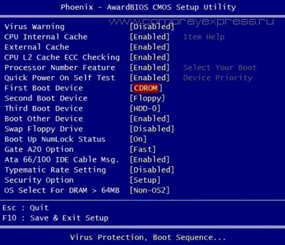
AWARD (Phoenix) BIOS

When you enter the BIOS, you will see one of two images presented, depending on the manufacturer. Next, carefully look at the screenshots and follow the instructions. If you have AMI BIOS:
We move along the menu to the right to the item boot.
On the page boot select an item Boot Device Priority.

We put the drive in the second (after Floppy) or first (whichever is more convenient) line. The main thing is that the hard drive is below the drive in this list. Devices can be selected using keys + And − , as well as from the menu ( see screenshot), which is called by pressing Enter.
You have bootable CD-DVD disc and you want to install an operating system on your computer, in order to do this you will need tune accordingly BIOS and boot from disk. We can also use the device selection in the boot menu, but this function is not always present, for example. on old motherboards. There is also no universal button for logging in. BIOS or boot menu. Many motherboard manufacturers assign different keys.
The surest way to identify such keys is to read the documentation for this laptop or computer, but no matter what key it is, you must always press it at the very beginning of loading. As soon as you turn on your computer, the program located in the BIOS automatically starts. BOOT-ROUTINE, which in turn calls the subroutine POST(English) Power-On Self Test), it checks the processor, random access memory (RAM), hard drive (HDD), motherboard elements and other main peripherals. One short the signal indicates that such a self-test completed successfully. This is what the passage might look like POST:
The most common key to enter the BIOS is DEL, we will give other options below. On the screen you see the following invitation: " Press DEL to run Setup", i.e. press the key DEL to log in BIOS. Also during the passage POST A graphical splash screen may be displayed that indicates the name of the computer or motherboard manufacturer.
List of the most common keys to enter the boot menu:
Acer- Esc or F12 or F9; Asrock- F11; Asus- Esc or F8; Compaq- Esc or F9; Dell- F12; ECS - F11; Fujitsu Siemens- F12; Gigabyte- F12; HP- Esc or F9; Intel- F10; Lenovo- F12; MSI(Micro-Star) - F11; Packard Bell- F8; Samsung- Esc; Sony Vaio- F11; Toshiba- F12
The menu for selecting boot devices looks something like this:

You just need to select the desired device from the list and click Enter.
List of the most common keys to enter BIOS Setup : ABIT-Del; Acer(Aspire, Altos, Extensa, Ferrari, Power, Veriton, TravelMate) - F2 or Del; Acer(old models) - F1 or Ctrl+Alt+Esc; ASRock- F2 or Del; ASUS-Del; BIOSTAR-Del; Chaintech-Del; Compaq(Deskpro, Portable, Presario, Prolinea, Systempro) - F10; Compaq(old models) - F1, F2, F10 or Del; Dell(Dimension, Inspiron, Latitude, OptiPlex, Precision, Vostro, XPS) - F2; Dell(old models) - Ctrl+Alt+, or Fn+Esc, or Fn+F1, or Del, or Reset twice; ECS (Elitegroup)- Del or F1; eMachines(eMonster, eTower, eOne, S-Series, T-Series) - Tab or Del; eMachines(some older models) - F2; Foxconn-Del; Fujitsu(Amilo, DeskPower, Esprimo, LifeBook, Tablet) - F2; GIGABYTE-Del; Hewlett-Parkard(HP Alternative, Tablet PC) - F2 or Esc, or F10, or F12; Hewlett-Parkard(OmniBook, Pavilion, Tablet, TouchSmart, Vectra) - F1; Intel- F2; Lenovo(3000 Series, IdeaPad, ThinkCentre, ThinkPad, ThinkStation) - F1 or F2; Lenovo(old models) - Ctrl+Alt+F3, Ctrl+Alt+Ins or Fn+F1; MSI(Micro-Star) - Del; Pegatron- F2, F10 or Del; Samsung- F2; Sony(VAIO, PCG-Series, VGN-Series) - F1, F2 or F3; Toshiba(Portege, Satellite, Tecra) - F1 or Esc.
AMI BIOS - changing device boot priority.
When changing settings and navigating the BIOS menu, use the Enter, +/-, and arrow keys on your keyboard. Use the arrows to move to the tab Boot and select Boot Device Priority:

Here we will see boot sequence: floppy drive first ( Floppy Drive), then hard drive ( Hard Drive), and the third device is turned off ( Disabled). If you want to boot from a disk, then you need the first device in this list to be a CD-DVD drive. Use the arrows to switch to the first device ( 1st Boot Device), press the key Enter and in the menu that appears, select CDROM. Booting from a flash drive is done in the same way.

To exit the BIOS while saving the settings you made ( Save and Exit), press the key F10 and confirm ( Ok) key Enter.

Phoenix-Award BIOS - changing device boot priority
Select from the menu Advanced BIOS Features and enter ( Enter).

Here, if we want to boot from the drive, we need to make sure that this device came first on the list. Use the arrows to switch to the first boot device ( First Boot Device) and change to CDROM. Then exit, saving the settings you made ( Save and Exit), by pressing F10.
Error sounds when passing Post
During the initial self-test of the system (pass Post) errors may occur. If they are not critical, then after a certain message is displayed, the computer will continue to boot. If serious errors are detected, the computer system will try to inform the user about them, but often it is impossible to display such information on the screen.
In this case, you will need to be guided sound signals(they are supplied by the system speaker, speaker, upon completion of the procedure Post). Using them, the system reports the results of self-testing. Below is list of such signals for different BIOS versions ( BIOS). Therefore, if your computer beeps, then you can easily determine if your PC is faulty.
AWARD BIOS signals:
No signals
Continuous beep- the power supply is faulty.
1 short- no errors found.
2 short- minor errors found.
3 long
1 long and 1 short- problems with RAM.
1 long and 2 short- problem with the video card.
1 long and 3 short- an error occurred while initializing the keyboard.
1 long and 9 short- an error occurred when reading data from the permanent memory chip.
1 long repeating- memory modules are installed incorrectly.
1 short repeating- problems with the power supply.
AMI BIOS signals:
No signals- the power supply is faulty or not connected to the motherboard.
1 short- no errors found.
2 short- RAM parity error.
3 short- an error occurred during the operation of the first 64 KB of main memory.
4 short- the system timer is faulty.
5 short- the central processor is faulty.
6 short- the keyboard controller is faulty.
7 short
8 short- video memory is faulty.
9 short
10 short- it is impossible to write to CMOS memory.
11 short- external cache memory (installed in slots on the motherboard) is faulty.
1 long and 2 short- the video card is faulty.
1 long and 3 short- the video card is faulty.
1 long and 8 short- problems with the video card or the monitor is not connected.
PHOENIX BIOS signals:
1-1-3 - error in writing/reading CMOS data.
1-1-4 - checksum error on the contents of the BIOS chip.
1-2-1 - the motherboard is faulty.
1-2-2 - DMA controller initialization error.
1-2-3 - error when trying to read/write to one of the DMA channels.
1-3-1 - RAM regeneration error.
1-3-3
1-3-4 - error when testing the first 64 KB of RAM.
1-4-1 - the motherboard is faulty.
1-4-2 - RAM testing error.
1-4-3 - system timer error.
1-4-4 - error accessing the I/O port.
3-1-1 - error in initializing the second DMA channel.
3-1-2 - error initializing the first DMA channel.
3-1-4 - the motherboard is faulty.
3-2-4 - keyboard controller error.
3-3-4 - video memory testing error.
4-2-1 - system timer error.
4-2-3 - line error A20. The keyboard controller is faulty.
4-2-4 - error when working in protected mode. The CPU may be faulty.
4-3-1 - error when testing RAM.
4-3-4 - real time clock error.
4-4-1 - Serial port testing error. The error may be caused by a device using this port.
4-4-2 - error when testing the parallel port. The error may be caused by a device using this port.
BIOS Setup Utility screens and descriptions are for reference only and may not correspond to what you see on your computer screen - based on a 2005 Intel i915PL chipset based motherboard for Intel (Socket 775) processors.
Main Menu - Main menu.
To allow the user to change basic settings for system and hardware parameters, the BIOS ROM has a built-in BIOS Setup program. The information is stored in battery-backed CMOS memory, and is thus retained when the main power is removed. In general, the information stored in CMOS RAM will not change unless something changes to the system, such as replacing a hard drive or adding a new device.
In some cases, the CMOS battery may fail, causing all CMOS information to be reset. If this happens, you will need to replace the CMOS battery and reconfigure the BIOS.
To enter the setup programs (SetupPprogram):
After turning on the computer, hold down the during self-test (POST). The BIOS setup utility CMOS SETUP UTILITY will open (Figure 1).
Figure 1. CMOS setup utility.
The main menu contains all the main settings sections. Select the section of the settings you want to configure. The selection is made by moving the cursor (using the cursor control arrows) and then pressing the key
1. Standard CMOS Setup - Standard CMOS settings
Select STANDARD CMOS FEATURES from the main menu (Figure 2). This section allows the user to configure basic system parameters, such as the current time and date, type of installed hard drive, type of floppy drive, and type of video adapter. The amount of RAM is automatically detected by the BIOS and displayed on the screen for information. When an item is highlighted (using the cursor arrows), the contents of the item can be changed by pressing keys Figure 2. Standard CMOS settings. Note: Selecting this section allows the user to change the settings of the parameters listed in this section. It shows the default settings set by the manufacturer. Keystroke Figure 3. Advanced BIOS settings. CPU Feature This option is only available for Pentium processors with the Prescott core. Here you set the sequence of enumerating the hard drives from which the system will boot. Figure 3-1. CPU L1&L2 Cache (Internal and external processor cache memory (L1 and L2)). CPU L3 Cache (Processor Level 3 Cache). Hyper-Threading Technology. First/Second/Third/Other Boot Device ( P first/ IN second/ T retier/ D other device to download).
2. Advanced BIOS Features - Additional BIOS settings.


This setting controls the state of the processor's internal and external cache memory.
This setting controls the state of the processor's Level 3 cache.
Options: Enabled, Disabled.
Note:
It is recommended to enable Hyper-Threading technology for systems running Windows XP and Linux 2.4, and disable it for earlier operating systems.
Includes processor Hyper-Threading technology.
Options: Enabled, Disabled.
The BIOS attempts to load the operating system from devices in the sequence defined in this paragraph.
Options: Floppy, LS120, Hard Disk, CDROM, ZIP100, USB-FDD, USB-CDROM, LAN, Disabled (device not used for booting).
When this option is enabled, the system tries to load the operating system from other devices not specified as the first/second/third device to boot.
Options: Enabled, Disabled.
Boot Up Floppy Seek (Search for floppy drive during boot).
When this option is enabled, the capacity of floppy drives is determined when the system boots. This feature may be useful if you are using an older 360KB floppy drive.
Options: Enabled, Disabled.
Boot Up NumLock Status ( WITH NumLock state during boot).
Determines the state of NumLock when the system boots.
Options:
On: The numeric keypad operates in numeric mode.
Off: The numeric keypad operates in cursor control mode.
Security Option (Access restriction).
This item allows you to restrict access to the system and the BIOS setup program, or only to the BIOS setup program.
System: The system will not boot and access to the BIOS setup utility will be denied until the correct password is entered.
Setup: The system will boot, but access to the BIOS setup utility will be denied until the correct password is entered.
APIC Mode - R APIC mode.
This item allows you to enable APIC (Advanced Programmable Interrupt Controller) functionality. APIC is an Intel chip that performs symmetric multiprocessing (SMP) computing on Pentium systems.
Options: Enabled, Disabled.
HDD S.M.A.R.T. Capability ( P S.M.A.R.T technology support).
S.M.A.R.T. (Self-Monitoring, Analysis and Alert Technology) is a diagnostic technology that allows you to monitor and predict the performance of devices. The software to support this technology is located both on the drive and on the computer itself. If a device failure is predicted, the software installed on the computer, using the Client WORKS S.M.A.R.T. client application, warns the user of the impending condition and suggests actions to save the information.
Options: Enabled, Disabled.
Full Screen LOGO Show - Displays the logo on full screen.
Displays a full-screen logo image during loading.
Options: Enabled, Disabled.
3. Advanced Chipset Features - Advanced chipset settings.
When you select this section, the following menu will be shown (Figure 4).

Figure 4. Advanced chipset settings.
DRAM Timing Selectable - IN Selecting timing parameters of DRAM memory.
When you select the “By SPD” value, the memory timing parameters will be set in accordance with the Intel Serial Presence Detection specification.
Options: Manual, By SPD.
CAS# Latency Time - Z delaysignalCAS.
This parameter allows you to set the number of clock cycles required after the CAS (Column Access Strobe) signal before the data read operation begins.
Options: 2.0, 2.5, 3.0, Auto.
DRAM RAS# to CAS# delay - Z delay between RAS and CAS signals
This parameter defines temporary system memory parameters such as CAS (Column Address Strobe) and RAS (Row Address Strobe).
Options: 2, 3, 4, 5, Auto.
DRAM RAS# Precharge - recharging time using the row selection signal.
This parameter determines the number of clock cycles required to return the data to its previous position to close a memory bank, or the number of clock cycles required for a memory page to execute a command to activate the next memory bank.
Options: 2, 3, 4, 5, Auto.
Precharge Delay (tRAS) - M minimum duration of the RAS signal.
This parameter determines the number of clock cycles required after the memory bank activation signal before recharging occurs (sets the minimum width of the RAS signal).
Options: Auto, 4~15.
SystemBIOSCacheable -
TO cachingBIOS'A.
This option allows the BIOS to be cached in RAM for faster command execution.
Options: Enabled, Disabled.
Video BIOS Cacheable - TO BIOS video ashing.
This option allows BIOS video to be cached in RAM for faster command execution.
Options: Enabled, Disabled.
4. Integrated Peripherals - Built-in peripherals.

Figure 5. Embedded peripherals.
Realtek Lan BOOT ROM.
Enables/disables Boot ROM of the integrated Realtek network card for booting from the local network.
- PCI Express Function - Operation tires PCI Express.
Move the cursor to the PCI Express Function section and press the key

Figure 5-1.
PCI-
Ex1
Func 1 (PCI-
Exp2)/
PCI-
Ex1
Func 2 (PCI-
Exp3).
This option allows you to select the mode Enabled, Disabled.
PCI-E Compliancy Mode.
This option allows you to select PCI-E Compliancy mode.
Options: V1.0a, V1.0
- Chipset IDE Devices - Integrated IDE devices.
Move the cursor to the IDE Function Setup section and press the key

Figure 5-2.
Delay For HDD (Secs).
This item allows you to set a longer delay time before scanning the hard drive begins during system boot. Some hard drives may require a longer latency to be detected correctly.
Options: 0 ~ 15sec.
IDE HDD Block Mode.
IDE HDD Block Mode allows the controller to access blocks of sectors rather than one sector at a time.
Options: Enabled, Disabled.
IDE DMA transfer access.
Automatic data transfer between system memory and IDE device with minimal CPU usage. Allows you to increase bandwidth and free up the processor for other tasks.
Options: Enabled, Disabled.
Chipset Primary (Secondary) PCI IDE.
The motherboard supports two channels of the regular IDE interface and one channel of the Serial ATA interface. Select "Enabled" to configure each channel.
If you are not using the onboard IDE connector, set the Onboard Primary (Secondary) PCI IDE settings to Disabled.
IDE Primary/Secondary Master/Slave PIO.
The four IDE PIO (Programmable Input/Output) fields allow you to set the PIO mode (0-4) for each of the four IDE devices supported by the integrated IDE controller. Modes 0 to 4 provide progressively higher performance. In Auto mode, the system automatically determines the best mode for each device.
Options: Auto, Mode 0~4.
IDE Primary/Secondary Master/Slave UDMA.
Selecting the operating mode of the IDE device. Using Ultra DMA-33/66/100 technology is only possible if your IDE hard drive supports it and the DMA driver is installed in the operating system. If both your hard drive and operating system support Ultra DMA-33/66/100, set this option to Auto to enable UDMA mode in the BIOS.
Options: Auto, Disabled.
*** On-Chip Serial ATA Setting ***
Setting up the integrated Serial ATA interface.
Chipset Serial ATA.
This item sets the operating mode of the SATA interface. In Combined mode, the SATA port will replace one of the traditional IDE Primary or Secondary ports. Enhanced mode will allow SATA to work simultaneously with Parallel-ATA ports.
Options: Disabled, Auto, Combined Mode, Enhanced Mode, SATA Only.
PATA IDE Mode.
This item is only available when the integrated SATA controller is in Combined mode. The value "Primary" will make the PATA IDE port the Primary port, and the remaining SATA ports will become Secondary. Likewise, the value "Secondary" will make the PATA IDE port a Secondary port and the SATA ports a Primary port.
Options: Primary, Secondary.
- Onboard Device Setup - Configuring built-in devices.
Move the cursor to the Onboard Device section and press the key

Figure 5-3.
USB Controller.
Includes USB controller.
USB 2.0 Controller.
Includes EHCI controller (USB 2.0).
Options: Disabled, Enabled.
USB Keyboard Support.
Enable/disable USB keyboard support when working in the DOS operating system.
USB Mouse Support.
Enable/disable USB mouse support when working in the DOS operating system.
Options: Enabled, Disabled.
AC97 Audio.
This option allows you to disable the integrated audio controller.
Options: Auto, Disabled.
Realtek Lan Device.
Includes an integrated LAN network interface.
Options: Enabled, Disabled.
- Legacy Devices - Setting up legacy devices.
Move the cursor to the Legacy Devices section and press the key

Figure 5-4.
Onboard FDC Controller - AND integrated floppy drive controller.
Select "Enabled" if you intend to use the integrated floppy drive controller. If you want to install an external controller or the system does not have a floppy drive, select the “Disabled” value.
Options: Enabled, Disabled.
Onboard Serial Port 1 - AND integrated P serial port 1.
Select the base address and interrupt number for integrated serial port No. 1.
Onboard IrDA Port - AND integrated infrared port.
Select the base address and interrupt number for the integrated infrared port.
Options: 3F8/IRQ4, 2E8/IRQ3, 3E8/IRQ4, 2F8/IRQ3, Disabled, Auto.
Onboard Parallel Port - AND integrated parallel port.
Integrated parallel LPT port configuration
Options: 378/IRQ7, 278/IRQ5, 3BC/IRQ7, Disabled.
Parallel Port Mode - R Parallel port operating mode.
Allows you to select the operating mode of the parallel port.
Options: SPP, EPP, ECP, ECP+EPP.
EPP Mode Select - IN choiceregimeEPP.
Allows you to select the EPP mode of the parallel port.
Options: EPP1.9, EPP1.7.
ECP Mode USE DMA - AND Using DMA in ECP mode.
Allows you to select DMA1 or DMA3 to use in ECP mode.
Options: 1, 3.
5. Power Management Setup - Power management settings.
Select “Power Management Setup” from the main menu (Figure 6). This section allows the user to change power management settings and IRQ signals. In general, these parameters should not be changed unless absolutely necessary.

Figure 6. Power management settings.
POWER ON Function.
Allows you to turn on the computer's power based on a signal from the keyboard, mouse, or by pressing a specified key combination.
Options: Disabled, Any Key, Mouse, Both (Any Key + Mouse).
PwrOn After Pwr-Fail - IN switching on after a power failure.
This parameter allows you to determine how the system behaves when power is restored.
Off: The system remains off.
Former- S ts: The system returns to the state it was in when the power was lost.
Power Management - U nutrition management.
This option allows you to select the power management mode. The default value is User Mode.
Max. S aving: Maximum energy saving. The inactivity period for all modes is 1 minute.
Min. S aving: Minimal energy saving. The period of inactivity for all modes is 1 hour.
User Define: Allows you to manually set time periods for energy saving modes.
Video Off Method - WITH way to turn off the screen.
This item allows you to select how to turn off the screen in energy-saving modes. The default value is “V/H Sync+Blank”.
V/H Sync+Blank: The system disables the vertical and horizontal scan circuits and writes a blank frame to the video buffer.
DPMSSupport: Select this option if your monitor supports the VESA (Display Power Management Signaling) DPMS standard. Use the software that came with your video devices to configure power management settings.
Blank: The system only writes an empty frame to the video buffer.
Suspend Mode - R suspend mode.
The system automatically turns off all devices except the processor after a specified period of system inactivity.
Options: Off, 1, 2, 4, 6, 8, 10, 20, 30, 40 minutes and 1 hour.
HDD Power Down - Disabling hard drives.
Turns off power to hard drives after a specified period of system inactivity.
Options: Disabled, 1~15min.
Soft-Off by PBTN - P Programmed shutdown with the power button.
Selecting the operating mode of the power button. Default value is "Instant Off"
Instant O ff: Immediately turns off the system.
Delay 4 S second: Turns off the system after a 4-second press delay. When you briefly press the power button, the system will enter Suspend mode. Press the power button again to return the system to normal operation.
Wake-Up by PCI Card - P Wake up on a signal from PCI.
Determines whether the system can return from S3/S4 mode based on a signal from a USB device.
Options: Enabled, Disabled.
Resume by Alarm - P Wake up by timer.
Allows you to set the day of the month and time (hh:mm:ss) when the turned off system will be turned on.
Options: Enabled, Disabled.
6. PNP/ PCI Configuration- ConfigurationPNP/ PCI.
This section allows you to modify PCI IRQ signals when installing various PCI expansion cards.
IN attention: TO IRQ conflicts may prevent the system from detecting some devices.

Figure 7. PNP/PCI configuration.
Init Display First - Determining the main video adapter.
Allows you to select the order in which video adapters are initialized when the system boots.
Options: PCI Slot, PCIEx.
Resources Controlled By - TO controlresources.
Determines how PNP/PCI resources are controlled. Default value is Auto (ESCD)
Manual: PNP card resources are controlled manually. The "IRQ Resources" field becomes available and you can what IRQ-X and DMA-X values are assigned to integrated and PCI devices.
Auto: The BIOS automatically assigns interrupt resources.
PCI/VGA Palette Snoop - TO VGA palette adjustment for PCI video cards.
This item is intended to solve problems with some non-standard VGA cards.
Options: Enabled, Disabled.
***
P PCI Express related items***
Maximum Payload Size.
Sets the maximum packet size (in bytes) for PCI Express devices.
Options: 128, 256, 512, 1024, 2048, 4096.
Interrupt requests are used in accordance with the table:

Table 7-1.
When using PCI cards in slots with shared IRQs, make sure their drivers support Shared IRQ mode or that the cards do not require an IRQ assignment. IRQ conflicts between two PCI groups will lead to unstable system operation or inoperability of these cards.
7. PC Health Status - Setting up hardware monitoring.

Figure 8. Setting up hardware monitoring.
Show PC Health in POST - P provide summary during loading.
When this feature is enabled, hardware monitoring system information is displayed on the screen during bootup.
Options: Enabled, Disabled.
Current System/CPU Temperature.
Shows the current chipset/processor temperature.
Current Power/CPU/System FAN Speed.
Shows the current rotation speed of the power supply/processor/case fans in revolutions per minute.
VDIMM
DIMM memory voltage level.
VChip
Chipset voltage level.
VCore
Processor core voltage level (Vcore).
Vbatt(V)
Battery voltage level.
+12V, VCC, 5VSB (V)
Switching power supply voltage levels.
ACPI Shutdown Temperature - T system shutdown temperature.
The temperature at which the computer will shut down to prevent damage from overheating (requires ACPI mode to be enabled in the Power Management section, and ACPI mode to be supported by the operating system). Default value: Disabled.
Available options: 60°C/140°F to 75°C/167°F in 5°C increments.
- SmartFan Function - AND Intelligent fan control.
Move the cursor to the SmartFan Function section and press the key

Figure 8-1.
Smart CPU FAN Function.
This item allows you to set the method for controlling the fan rotation speed. The "Full Speed" method sets the fan duty cycle to 100%. When you select the “By Duty Cycle” method, you can directly set the fan duty cycle. The “By Temperature” method allows you to calculate the fan rotation speed depending on the temperature range.
Below is an example of using the "By Tempeature" method.
Current CPU Temperature/Fan Speed.
Displays the current CPU temperature/fan speed.
Example of how the function works S martFan:
Table 8-2.
You only need to set the parameters marked in gray in the figure. The system will automatically calculate the intermediate temperatures Temp LM and Temp MH and the corresponding duty cycle values Duty LM and Duty MH.
. The performance of the Smart CPU FAN function depends on the fan design. Most fans have built-in thermistors and can independently regulate the rotation speed. Some fans only allow duty cycle control over a very limited range of values.
. For best results, use the USDM utility to configure the fan.
8. Power BIOS Features - System overclocking settings.
This section allows you to configure various system overclocking options to achieve better performance.
Attention:
Overclocking a system requires in-depth understanding and can damage system components. We recommend not changing the values of these parameters for stable system operation.

Figure 9. Frequency/voltage setting.
Auto Detect PCI Clk - A Automatic detection of PCI bus frequency.
When enabled, automatically disables clocking on unused (empty) PCI slots, thereby reducing EMI.
Options: Enabled, Disabled.
Spread Spectrum Modulated - M modulated extended spectrum.
Enabling this option can significantly reduce electromagnetic interference generated by the system.
Options: Enabled, Disabled.
WatchDogFunction- Control function.
When this feature is enabled and the system overclocking fails before POST 26h, the system parameters will be automatically set to default values.
Options: Enabled, Disabled.
CPU CLOCK/SPEED - H CPU frequency/speed.
Allows you to increase the processor clock frequency in 1 MHz increments. Together with the processor frequency multiplication factor (“CPU Clock Ratio”), this parameter determines the operating frequency of the processor.
Clock frequency x TO multiplication factor = R operating frequency of the processor.
For example, if the processor runs at 2.4 GHz and the clock frequency is 200 MHz, then 200 MHz x 12 = 2.4 GHz.
Options: from 200 to 400 in 1 MHz steps.

Figure 9-1. The FSB frequency is 800 MHz.

Figure 9-2. The FSB frequency is 533 MHz.
Enter the processor frequency in decimal format.
The result of unsuccessful overclocking will be the absence of an image on the monitor screen. To resolve this issue, turn off the system power and turn it on again. While rebooting the system, keep the "Insert" key pressed. This will reset the BIOS settings to default values.
PCI Express Freq Control - U governing bodyfrequencytiresPCI Express.
Allows you to control the operating frequency of the PCI Express bus.
The “Enabled” value allows you to change its frequency in 1 MHz steps using the following item. Selecting the “Disabled” value will fix the PCI‑E bus frequency at 100 MHz. The "Auto" value will set the frequency according to the FSB bus.
Options: Auto, Enabled, Disabled.
PCI Express Freq - N Setting the PCI Express bus frequency.
Allows you to adjust the operating frequency of the PCIE bus in 1 MHz steps.

Figure 9-3. Enter the PCI Express frequency value in decimal format.
PCI FrequencySel- Setting the PCI bus frequency.
Allows you to select the PCI bus frequency.
Options: 33.3 MHz, 33.80 MHz, 34.28 MHz, 34.78 MHz, 35.29 MHz, 35.82 MHz, 36.36 MHz, 36.92 MHz, 37.50 MHz.
System Memory Frequency - N Adjusting the system memory frequency.
Allows you to set the DDR SDRAM clock multiplier to match the installed DIMMs. It is recommended to leave the default value. The available options depend on the FSB bus frequency.
Figure 9-4.
CPU Clock Ratio - N Setting the processor frequency multiplier.
Allows you to set the processor frequency multiplication factor. See CPU CLOCK/SPEED. If your processor's frequency multiplier is locked, this option is not available.
Voltage Adjust Menu - AND Changing voltage levels.
Move the cursor to the Voltage Adjust Menu section and press the key

Figure 9-5.
In the following paragraphs, "DefaultVoltage(Default Voltage)" means the manufacturer's settings, and "NewVoltage(New Voltage Value)” means the user-specified voltage.
CPU Vcore
This item allows you to change the processor core voltage Vcore.
Chipset Voltage
This item allows you to change the chipset voltage.
It is recommended to leave the default value.
VDIMM Voltage
This item allows you to change the voltage of DIMM memory modules.
It is recommended to leave the default value.


