Printer for the production of printed circuit boards. Direct inkjet printing of printed circuit board templates Conversion of the printer for printing on foil PCB
Lately I've been looking for ways to make it easier to make printed circuit boards. About a year ago, I came across an interesting article that described the process of modifying an inkjet Epson printer for printing on thick materials, incl. on copper textolite. The article described the modification of the Epson C84 printer, however, I had an Epson C86 printer, but because... I think the mechanics of Epson printers are similar for everyone, so I decided to try to upgrade my printer. In this article I will try to describe in as much detail as possible, step by step, the process of upgrading a printer for printing on copper-bonded PCB.
Necessary materials:
- Well, of course you will need the Epson C80 family printer itself.
- sheet of aluminum or steel material
- staples, bolts, nuts, washers
- a small piece of plywood
- epoxy or superglue
- ink (more on this later)
Tools:
- a grinder (Dremel, etc.) with a cutting wheel (you can try with a small monkey)
- various screwdrivers, wrenches, hexagons
- drill
- hot air gun
Step 1. Disassemble the printer
The first thing I did was remove the rear paper output tray. After this, you need to remove the front tray, side panels and then the main body.
The photos below show detailed process printer disassembly:


Step 2. Remove the internal parts of the printer
After the printer body is removed, it is necessary to remove some internal parts of the printer. First, you need to remove the paper feed sensor. We will need it later, so do not damage it when removing it.

Then, it is necessary to remove the central pressure rollers, because they may interfere with the feeding of the PCB. In principle, the side rollers can also be removed.

Finally, you need to remove the print head cleaning mechanism. The mechanism is held on by latches and can be removed very easily, but when removing, be very careful, because different tubes fit to it.


The printer disassembly is complete. Now let's start “lifting” it.
Step 3: Removing the print head platform
We begin the process of upgrading the printer. The work requires accuracy and the use of protective equipment (you need to protect your eyes!).
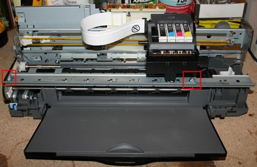
First you need to unscrew the rail, which is fastened with two bolts (see photo above). Unscrewed? We put it aside; we will need it later.

Now notice the 2 bolts near the head cleaning mechanism. We also unscrew them. However, on the left side it is done a little differently; the fasteners can be cut off there.
To remove the entire platform with the head, first, carefully inspect everything and mark with a marker the places where you will need to cut the metal. And then carefully cut the metal with a hand grinder (Dremel, etc.)


Step 4: Clean the print head
This step is optional, but since you have completely disassembled the printer, it is better to clean the print head right away. Moreover, there is nothing complicated about it. For this purpose I used regular ear sticks and glass cleaner.

Step 5: Install the print head platform. Part 1
After everything has been disassembled and cleaned, it is time to assemble the printer, taking into account the required clearance for printing on the PCB. Or, as jeepers say, “lifting” (i.e. lifting). The amount of lifting depends entirely on the material you are going to print on. In my modification of the printer, I planned to use a steel material feeder with a PCB attached to it. The thickness of the platform for supplying material (steel) was 1.5 mm, the thickness of the foil PCB, from which I usually made boards, was also 1.5 mm. However, I decided that the head should not press hard on the material, and therefore I chose a gap size of about 9 mm. Moreover, sometimes I print on double-sided PCB, which is slightly thicker than single-sided.

To make it easier for me to control the level of lift, I decided to use washers and nuts, the thickness of which I measured with a caliper. Also, I bought some long bolts and nuts for them. I started with the front feed system.
Step 6: Install the print head platform. Part 2

Before installing the print head platform, it is necessary to make small jumpers. I made them from corners that I sawed into 2 parts (see photo above). You can of course make them yourself.


Afterwards, I marked the holes for drilling in the printer. The bottom holes are very easy to mark and drill. Then, I immediately screwed the brackets into place.

The next step is to mark and drill the upper holes in the platform; this is somewhat more difficult to do, because everything should be on the same level. To do this, I placed a pair of nuts in the places where the platform joins the base of the printer. Using a level, make sure the platform is level. We mark the holes, drill and tighten with bolts.


Step 7. “Lifting” the print head cleaning mechanism
When the printer finishes printing, the head is “parked” in the head cleaning mechanism, where the head nozzles are cleaned to prevent them from drying out and clogging. This mechanism also needs to be raised a little.

I secured this mechanism using two corners (see photo above).
Step 8: Feed System
At this stage, we will consider the process of manufacturing the feed system and installing the material feed sensor.

When designing the feed system, the first challenge was installing the material feed sensor. Without this sensor the printer would not function, but where and how to install it? When paper passes through the printer, this sensor tells the printer controller when the beginning of the paper has passed and based on this data the printer calculates the exact position of the paper. The feed sensor is a conventional photosensor with an emitting diode. When paper passes (in our case, material), the beam in the sensor is interrupted.
For the sensor and feed system, I decided to make a platform out of plywood.

As you can see in the photo above, I glued several layers of plywood together in order to make the feed flush with the printer. In the far corner of the platform I attached a feed sensor through which the material will flow. I made a small cutout in the plywood to insert the sensor.


The next task was the need to make guides. To do this, I used aluminum corners, which I glued to the plywood. It is important that all angles are clearly 90 degrees and the guides are strictly parallel to each other. As the feed material, I used an aluminum sheet on which the copper-plated PCB will be placed and fixed for printing.


I made the material supply sheet from an aluminum sheet. I tried to make the sheet size approximately equal to A4 format. After reading a little on the Internet about the operation of the paper feed sensor and the printer in general, I found out that for the printer to work correctly, it is necessary to make a small cutout in the corner of the material feed sheet so that the sensor is triggered a little later than the feed rollers begin to spin. The length of the cutout was about 90mm.

After everything was done, I attached a regular sheet of paper to the feed sheet, installed all the drivers on the computer and made a test print on a regular sheet.
Step 9. Filling the ink cartridge

The last part of the printer modification is dedicated to ink. Regular Epson ink is not resistant to the chemical processes that occur during etching of a printed circuit board. Therefore, you need special ink, they are called Mis Pro yellow ink. However, this ink may not be suitable for other printers (non-Epson), because... other types of printheads may be used there (Epson uses a piezoelectric printhead). The online store inksupply.com offers delivery to Russia.

In addition to ink, I bought new cartridges, although of course you can use old ones if you wash them well. Naturally, to refill the cartridges you will also need a regular syringe. Also, I bought a special device for resetting printer cartridges (blue in the photo).
Step 10. Tests
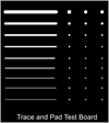
Now let's move on to printing tests. In the Eagle design program, I made several printable blanks, with tracks of varying thicknesses.


You can evaluate the quality of printing from the photographs above. And below is a video of printing:
Step 11: Etching
For etching boards manufactured using this method, only a ferric chloride solution is suitable. Other etching methods (copper sulfate, hydrochloric acid, etc.) may corrode Mis Pro yellow ink. When etching with ferric chloride, it is better to heat the printed circuit board using a heat gun, this speeds up the etching process, etc. Less “eating” of the ink layer.

The heating temperature, proportions and duration of etching are selected experimentally.


From time to time I need to make printed circuit boards for my crafts. LUT is an extremely capricious method for me - either the toner will melt and spread, or the quality of the paper will not work, or some other hemorrhoids - you need nerves of steel and iron. For photoresist, specific reagents and a laminator.
“What if we build a special machine for this? To print with paint right away?” I thought. “Remake the printer!” laziness reasonably remarked. A search on the Internet revealed that people successfully convert inkjet printers for printing on PCB, but this is a rather labor-intensive process (you need to finish and lift the frame with the print head, etc.), besides, I value my inkjet printer like Madame Gritsatsueva values her strainer (MFP, after all). But I had an unnecessary laser HP lj 6L lying around idle - in general, it was lying around. It was useful to look at the characteristics and accidentally came across (a cache of articles, just in case) on converting this particular printer into PCB. But the topic in the article was not fully revealed - in particular, it does not tell how to make the toner stick to the PCB foil, how to bake this toner later and, most importantly, there is no video demonstration of a working sample, so I brought this matter to mind on your own. I strongly recommend that you read the above-mentioned article, because I will not repeat what is described there in all details - there is no point in creating copy-paste. There are a lot of photos under the cut.
So, the alteration itself consists of little things - make a cut in the back wall, remove the bumper pad and the stove (so that the printed design does not smear). The heater temperature sensor must be replaced with a resistor with a resistance of 8.2 kOhm. I recommend doing it like this (just short-circuit the temperature sensor with a resistor so you don't have to mess with securing it):

There is no need to do anything to the connector that supplies the heating voltage. Disconnect the stove from it and that’s it.
Next, you need to work with the impact pad - this is what was located behind the paper pickup roller - it needs to be cut off, leaving only the sides. I'm sorry, but the photos are from unsawed back no - I forgot to take a photo, and when I came to my senses and came to my senses, everything had already been sawed off. I don’t know how it happened. Nightmare.
This is what it should look like:

Yes, I almost forgot: be careful with the paper flow sensor (it, or rather the upper arm of its flap, is located in that slot to the left of the paper pickup roller) - do not accidentally cut off its fasteners, otherwise the printer will not be able to control the end of the sheet in the feed path.
From time to time I need to make printed circuit boards for my crafts. LUT is an extremely capricious method for me - either the toner will melt and spread, or the quality of the paper will not work, or some other hemorrhoids - you need nerves of steel and iron. For photoresist, specific reagents and a laminator.
“What if we build a special machine for this? To print with paint right away?” I thought. “Remake the printer!” laziness reasonably remarked. A search on the Internet revealed that people successfully convert inkjet printers for printing on PCB, but this is a rather labor-intensive process (you need to finish and lift the frame with the print head, etc.), besides, I value my inkjet printer like Madame Gritsatsueva values her strainer (MFP, after all). But I had an unnecessary laser HP lj 6L lying around idle - in general, it was lying around. It was useful to look at the characteristics and accidentally came across (a cache of articles, just in case) on converting this particular printer into PCB. But the topic in the article was not fully revealed - in particular, it does not tell how to make the toner stick to the PCB foil, how to bake this toner later and, most importantly, there is no video demonstration of a working sample, so I brought this matter to mind on your own. I urgently I recommend that you read the above-mentioned article, because I will not repeat what is described there in all details - there is no point in creating copy-paste. There are a lot of photos under the cut.
So, the alteration itself consists of little things - make a cut in the back wall, remove the bumper pad and the stove (so that the printed design does not smear). The heater temperature sensor must be replaced with a resistor with a resistance of 8.2 kOhm. I recommend doing it like this (just short-circuit the temperature sensor with a resistor so you don't have to mess with securing it):

There is no need to do anything to the connector that supplies the heating voltage. Disconnect the stove from it and that’s it.
Next, you need to work with the impact pad - this is what was located behind the paper pickup roller - it needs to be cut off, leaving only the sides. I'm sorry, but there is no photo with the unsawed back part - I forgot to take a photo, and when I came to my senses and came to my senses, everything had already been sawed off. I don’t know how it happened. Nightmare.
This is what it should look like:

Yes, I almost forgot: be careful with the paper flow sensor (it, or rather the upper arm of its flap, is located in that slot to the left of the paper pickup roller) - do not accidentally cut off its fasteners, otherwise the printer will not be able to control the end of the sheet in the feed path.

But on the contrary, remove the flap from the paper presence sensor, and it will seem to the printer that there is always “paper”.

Back view:

That's all I wanted to clarify about the remodel. And now no less important points- toner sticking to the foil and fixing it using heat. 
And, of course, what we’ve all gathered here for is a video demonstration of the device’s operation:
That's all. This “machine” has made my life much easier. I have already successfully printed more than one board with its help, pah-pah. If all this is useful to someone, I will be very happy. Thank you for your attention.
From time to time I need to make printed circuit boards for my crafts. LUT is an extremely capricious method for me - either the toner will melt and spread, or the quality of the paper will not work, or some other hemorrhoids - you need nerves of steel and iron. For photoresist, specific reagents and a laminator.
“What if we build a special machine for this? To print with paint right away?” I thought. “Remake the printer!” laziness reasonably remarked. A search on the Internet revealed that people successfully convert inkjet printers for printing on PCB, but this is a rather labor-intensive process (you need to finish and lift the frame with the print head, etc.), besides, I value my inkjet printer like Madame Gritsatsueva values her strainer (MFP, after all). But I had an unnecessary laser HP lj 6L lying around idle - in general, it was lying around. It was useful to look at the characteristics and accidentally came across (a cache of articles, just in case) on converting this particular printer into PCB. But the topic in the article was not fully revealed - in particular, it does not tell how to make the toner stick to the PCB foil, how to bake this toner later and, most importantly, there is no video demonstration of a working sample, so I brought this matter to mind on your own. I urgently I recommend that you read the above-mentioned article, because I will not repeat what is described there in all details - there is no point in creating copy-paste. There are a lot of photos under the cut.
So, the alteration itself consists of little things - make a cut in the back wall, remove the bumper pad and the stove (so that the printed design does not smear). The heater temperature sensor must be replaced with a resistor with a resistance of 8.2 kOhm. I recommend doing it like this (just short-circuit the temperature sensor with a resistor so you don't have to mess with securing it):
There is no need to do anything to the connector that supplies the heating voltage. Disconnect the stove from it and that’s it.
Next, you need to work with the impact pad - this is what was located behind the paper pickup roller - it needs to be cut off, leaving only the sides. I'm sorry, but there is no photo with the unsawed back part - I forgot to take a photo, and when I came to my senses and came to my senses, everything had already been sawed off. I don’t know how it happened. Nightmare.
This is what it should look like:
Yes, I almost forgot: be careful with the paper flow sensor (it, or rather the upper arm of its flap, is located in that slot to the left of the paper pickup roller) - do not accidentally cut off its fasteners, otherwise the printer will not be able to control the end of the sheet in the feed path.
But on the contrary, remove the flap from the paper presence sensor, and it will seem to the printer that there is always “paper”.
Back view:
That's all I wanted to clarify about the remodel. And now no less important points are the adhesion of the toner to the foil and its fixation using heat.
And, of course, what we’ve all gathered here for is a video demonstration of the device’s operation:
That's all. This “machine” has made my life much easier. I have already successfully printed more than one board with its help, pah-pah. If all this is useful to someone, I will be very happy. Thank you for your attention.
Almost everyone involved in radio engineering is faced with the fact that as the number of boards being created increases, it takes a lot of effort and time to correctly draw the tracks. Not to mention their etching, tinning and soldering...
What if some of the processes can be automated? Certainly, we're talking about It’s not about assembly line production or putting circuit printing on a professional production line.
Yes, for myself. Moreover, along with a reduction in the time of transferring the circuit to the PCB comes:
1.High precision (even with simple inkjet printers you can achieve sufficient quality to transfer closely spaced tracks that are very difficult to draw by hand);
2. Elimination of errors (if the printed circuit board has already been drawn in detail in the program, its printed version will fully correspond to the intended layout, you will not accidentally draw the wrong track, shift the contact seat, etc.).
Solution options
1. Of course, if you produce a large number of printed circuit boards, then it’s time to think about purchasing professional equipment (for example, UV printers).
2.You can make a printing device yourself from scratch (assembled from guides, stepper motors, etc.).
3. Recycle an old and unnecessary printer.
Of all the above, the alteration sounds the most real.
The best donors to consider are (in descending order of priority):
1.Inkjet printers (black and white or color);
2.Laser printers.
It’s worth mentioning right away that many modern models are equipped with different ways protection from external interference. Manufacturers block printing from non-original cartridges, check ink consumption for each cartridge, etc.
Therefore, for remodeling, it is best to take old printing devices with a simple design and without any protection.
Example based on inkjet printer Epson C84
As an analogue, you can try to adapt the process for all devices from the C80 series.
The printer itself looks like this before modification:
Rice. 1. Printer appearance
Step by step instructions:
1.Remove the trays;
2.Remove the casing (outer casing). It should turn out like this.

Rice. 2. Start disassembling the printer
3. Disconnect and unscrew the paper feed sensor.
His appearance.

Rice. 3. Paper feed sensor
4.Remove the pressure rollers.

Rice. 4. Pressure rollers
5. Dismantle the system for cleaning the print heads.

Rice. 5. Printhead cleaning system
6.Unscrew and lift the platform with the print heads. Let's start with this rail.

Rice. 6. Dismantling the platform with print heads
7.Using an angle grinder with a small-diameter metal cutting disc, carefully cut off the platform. See photo.


Rice. 7. Platform cut
8.Now the free print platform can be raised to the required height (depending on what material you are going to print on). To do this, you will need jumpers (any metal plate with conveniently located holes will do).

Rice. 8. Jumpers on the printer body
9.Drill holes in the printing platform and attach to the base. This is the most important stage, the reason for which everything was started. "Lifting" (lifting) must be precisely calculated in advance. If you don’t get the dimensions right or position the printing platform crookedly, it will be difficult to redo it (re-measure and re-drill everything, or select new jumpers). It is best to use a lining of a given thickness at the gap setting stage.
We twist it.

Rice. 9. M installation of printing platforms
10.To prevent the ink from drying on the print head after using the printer, it is necessary to return the nozzle cleaning mechanism to its place. However, because the platform has been raised, the cleaning mechanism will also have to be raised. For example, like this.

Rice. 10. Installation of the nozzle cleaning mechanism
11.We make a platform for feeding the sheet (replacing the lower tray). The platform can be made of plywood, hardboard, etc. sheet materials that are on hand.

Rice. 11. Sheet feeding platform
12. We attach the guides (must be strictly parallel to each other) and the sheet feed sensor to the platform.

13. We replace the paper with durable sheet material (for example, an aluminum sheet, meaning A4 format), however, in order for the paper feed sensor to work correctly (it also changed its location after dismantling), a cutout (90 mm) should be made in the sheet.

Rice. 13. Sheet material
14.Install the drivers, connect the printer to the PC (as usual).
15. Refill the cartridge with Mis Pro yellow ink (only they are resistant to the chemical etching reaction using ferric chloride and are suitable for Epson nozzles with a piezoelectric head).
16.Print your diagram. We attach the textolite to an aluminum sheet.
17. We etch the board (only in a ferric chloride solution, to speed up the process you can heat it with a hairdryer).

Rice. 14. View of the assembled printer
Publication date: 24.01.2018
Readers' opinions
- Edward / 02/18/2019 - 11:58
Class! Respect and respect to you))) for a quality guide!)))


